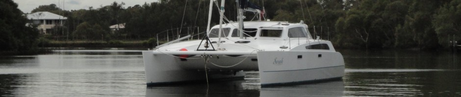
Now that we have launched, let’s have a quick look at the job from start to finish.
This was the first frame, cut on a CNC router. This first frame was nicely cut, better than I could have done by hand. So I went on to program the CNC machine to cut all the frames, with more features. The remainder of the frames were cut with the stringer notches already removed, and with scoring on one surface to mark out centreline and waterline to further aid the alignment of the frames on the strongback jig.
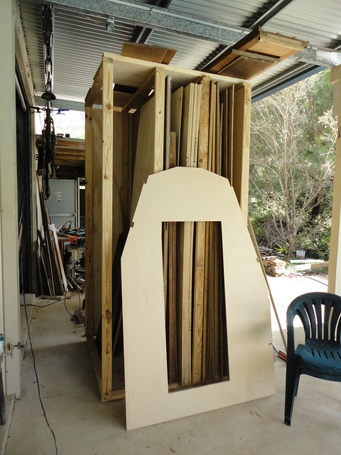
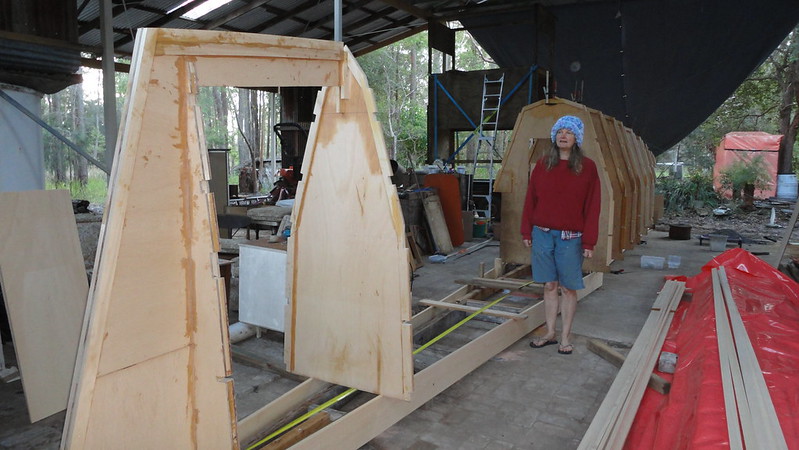
Here’s one of those enhanced frames standing in front of the storage rack that we built to hold the sheets of plywood and plastic ready for use.
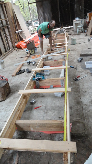
This is the strongback jig on which the hulls were built. I was lucky with the facilities for the build. I live on 100 acres in the bush, and had an old shed with a concrete floor. That shed was full of termites, so it came down to make way for the new boat shed. That shed was a massive effort to build, with a floor space of 14x8m with another 14x5m in skillions on each side. So the jig was mainly on a concrete slab, with metal tags dynabolted to the floor, with the bow section bolted down to brick paving that had been a lean-to on the side of the original shed. Behind me is the welder that put together the frame for the shed, and that timber rack for storing all the sheets of plywood and plastic.
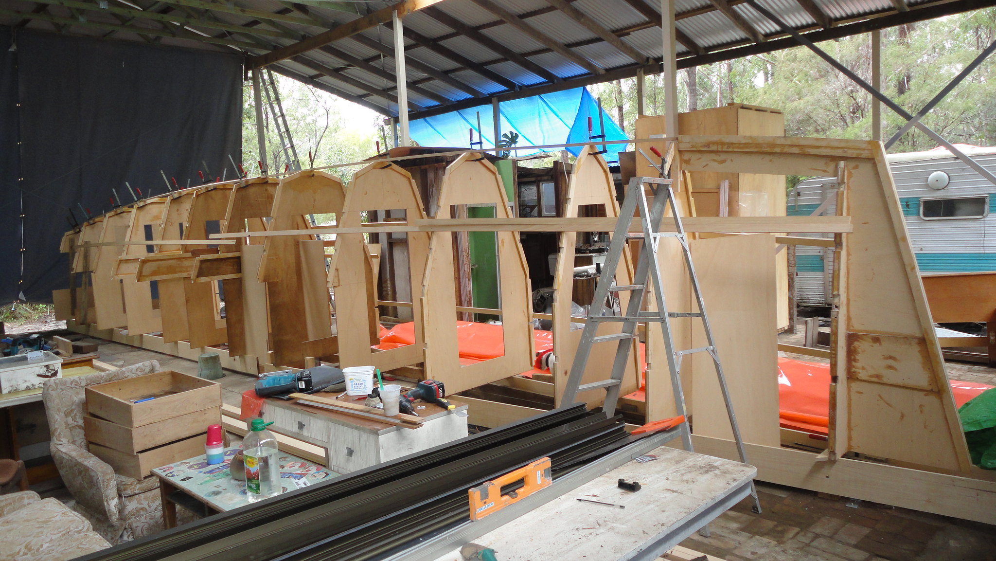
Here are the frames getting stood onto that strongback jig.
Stringers were clamped onto the frames to stabilise the structure while it was all checked for alignment prior to fitting the stringers into the notches in the frames.
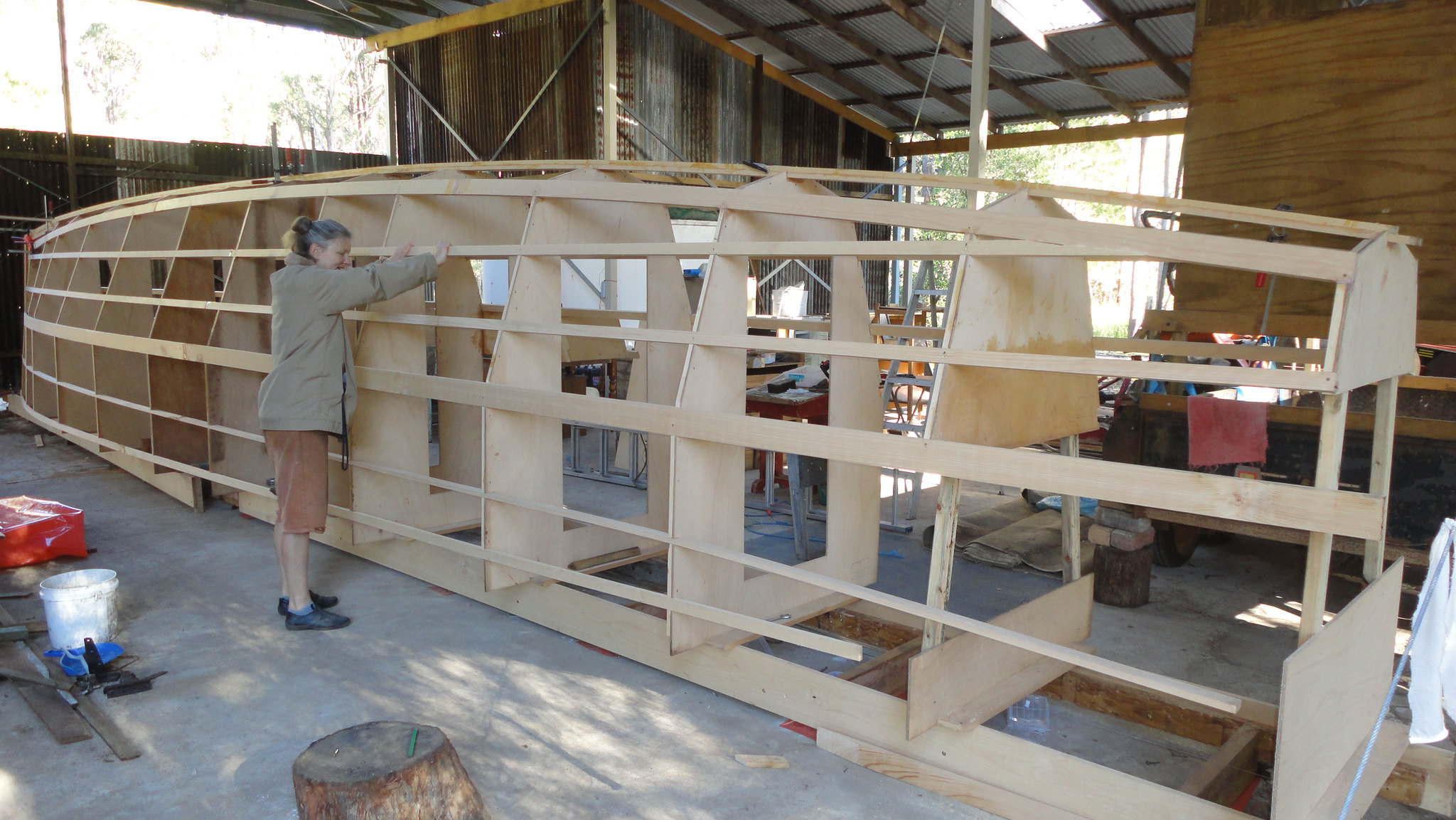
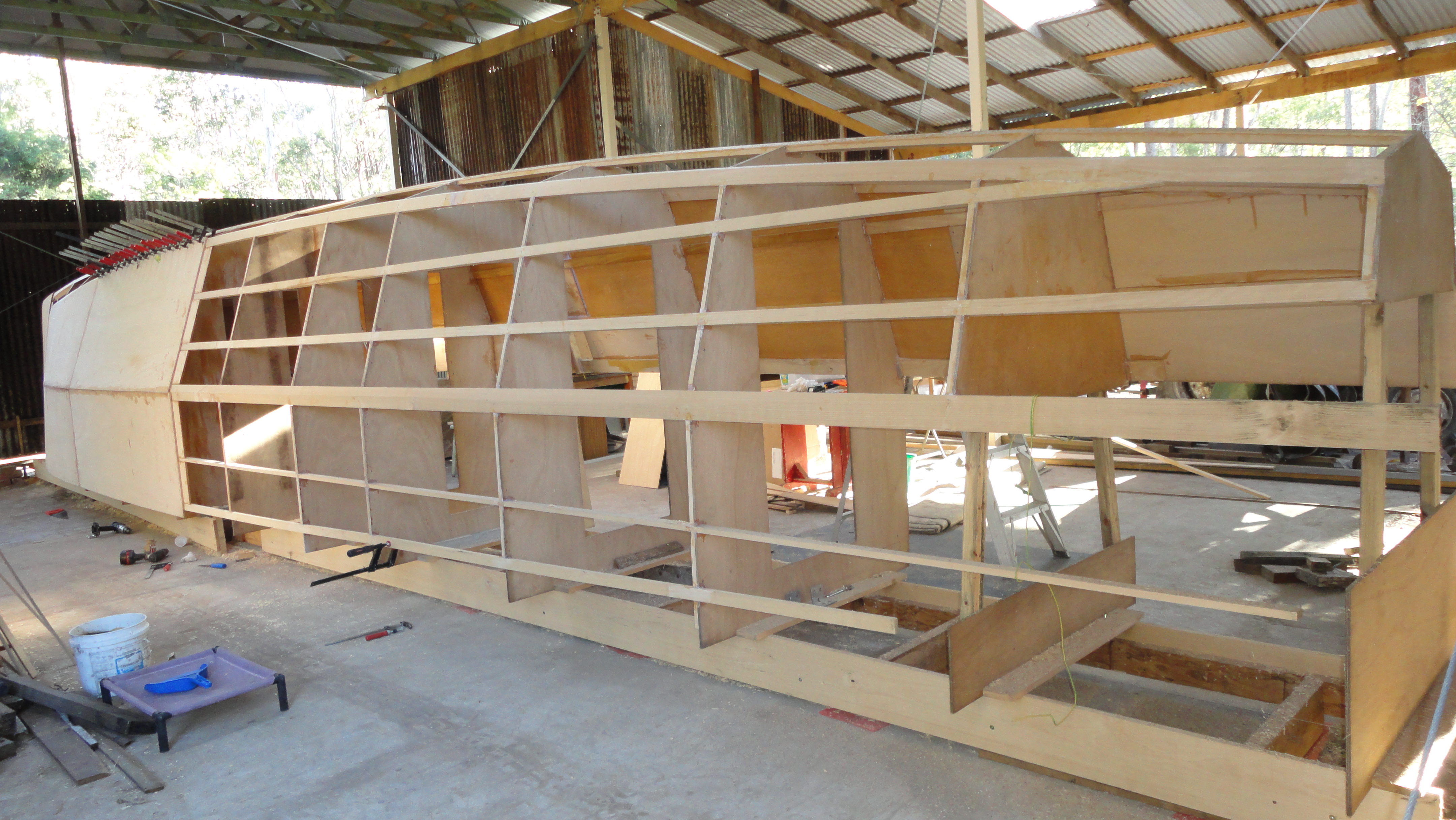
When straight, the stringers were glued into the notches and the temporary ones removed.

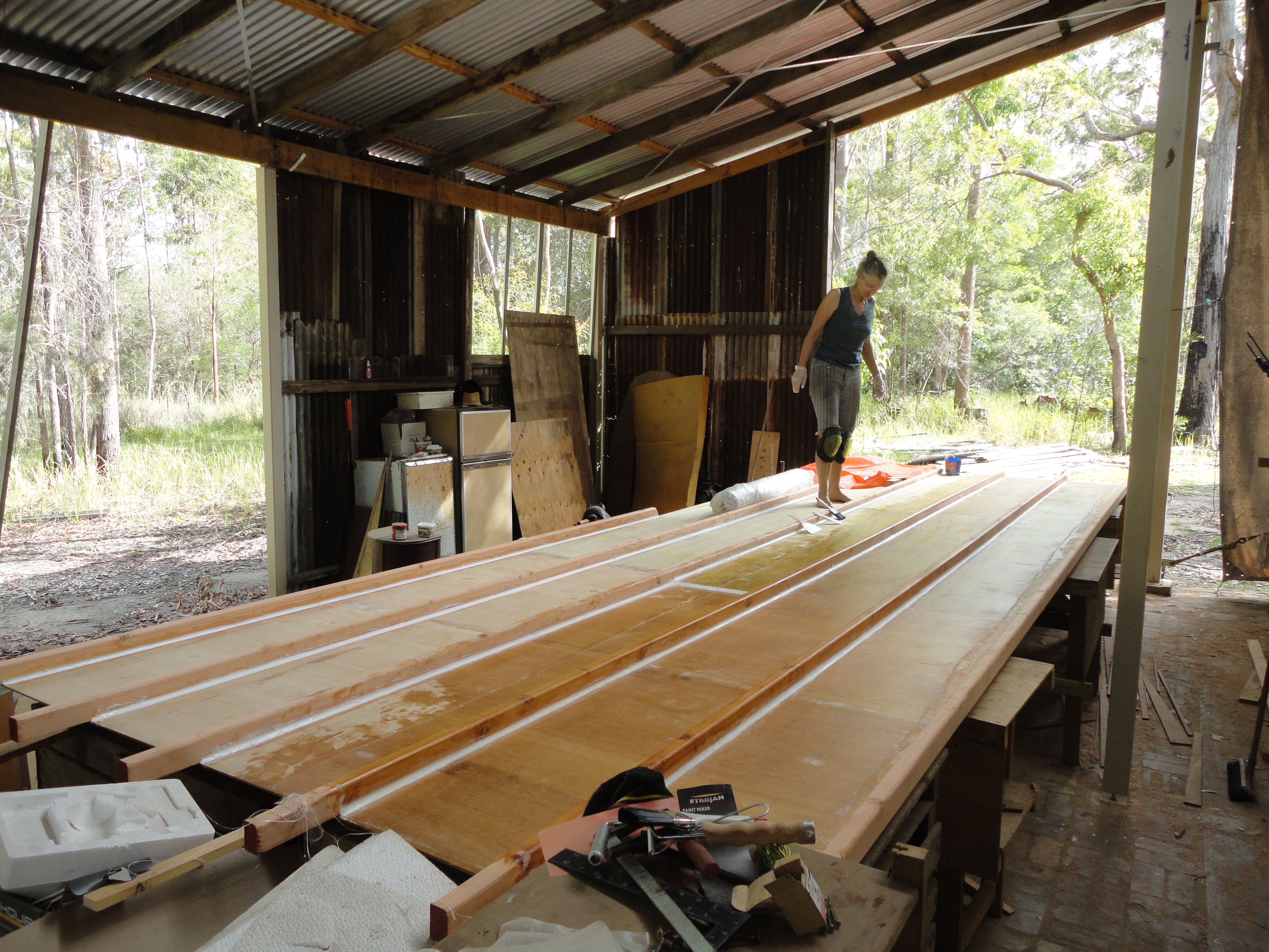
Now the sheeting could commence.
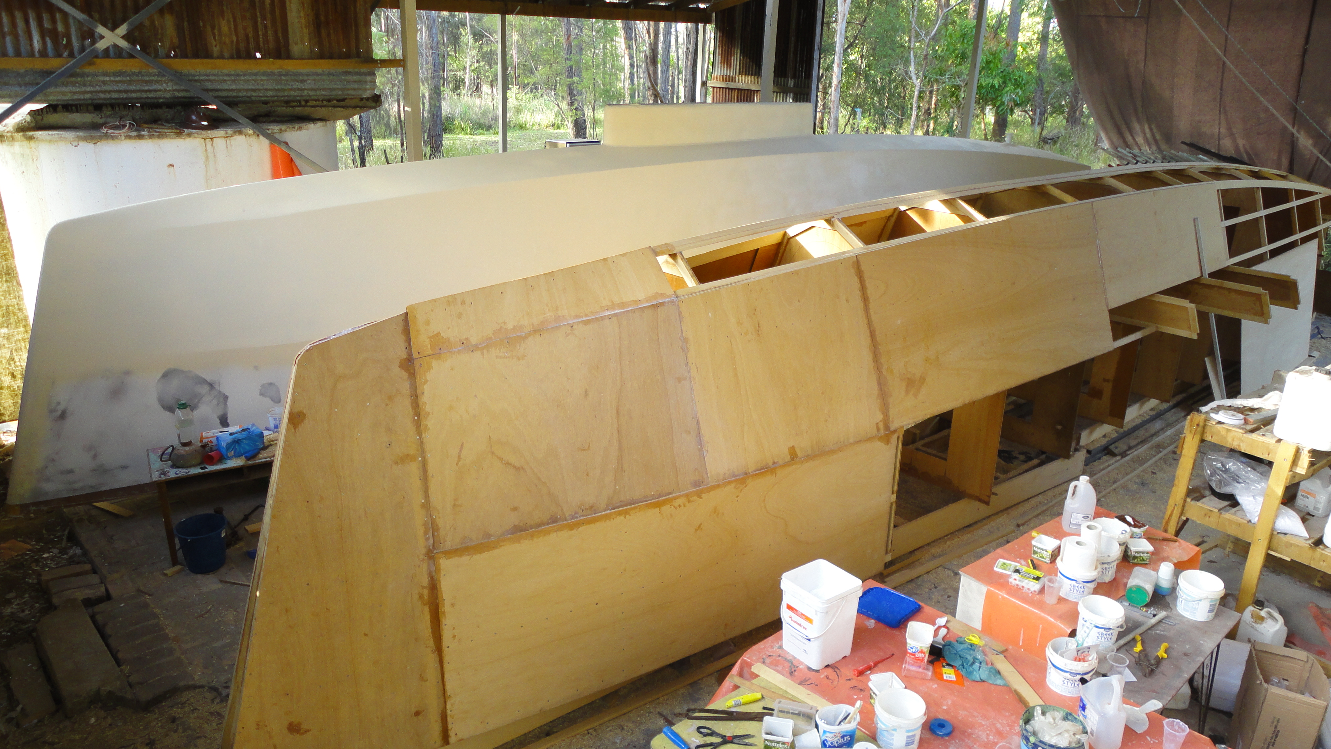
I didn’t exactly follow the instructions here. I had seen a few bows being sheeted, and thought there was too much end grain exposed at the fine angles at the chines. I commenced with a full sheet used vertical right at the bow before continuing with the horizontal sheets from there back. I checked this with the designer who had considered this but never tried it, but had no problems with me making this change. I think it actually lead to the butt blocks further back being in more convenient (less obvious) locations.
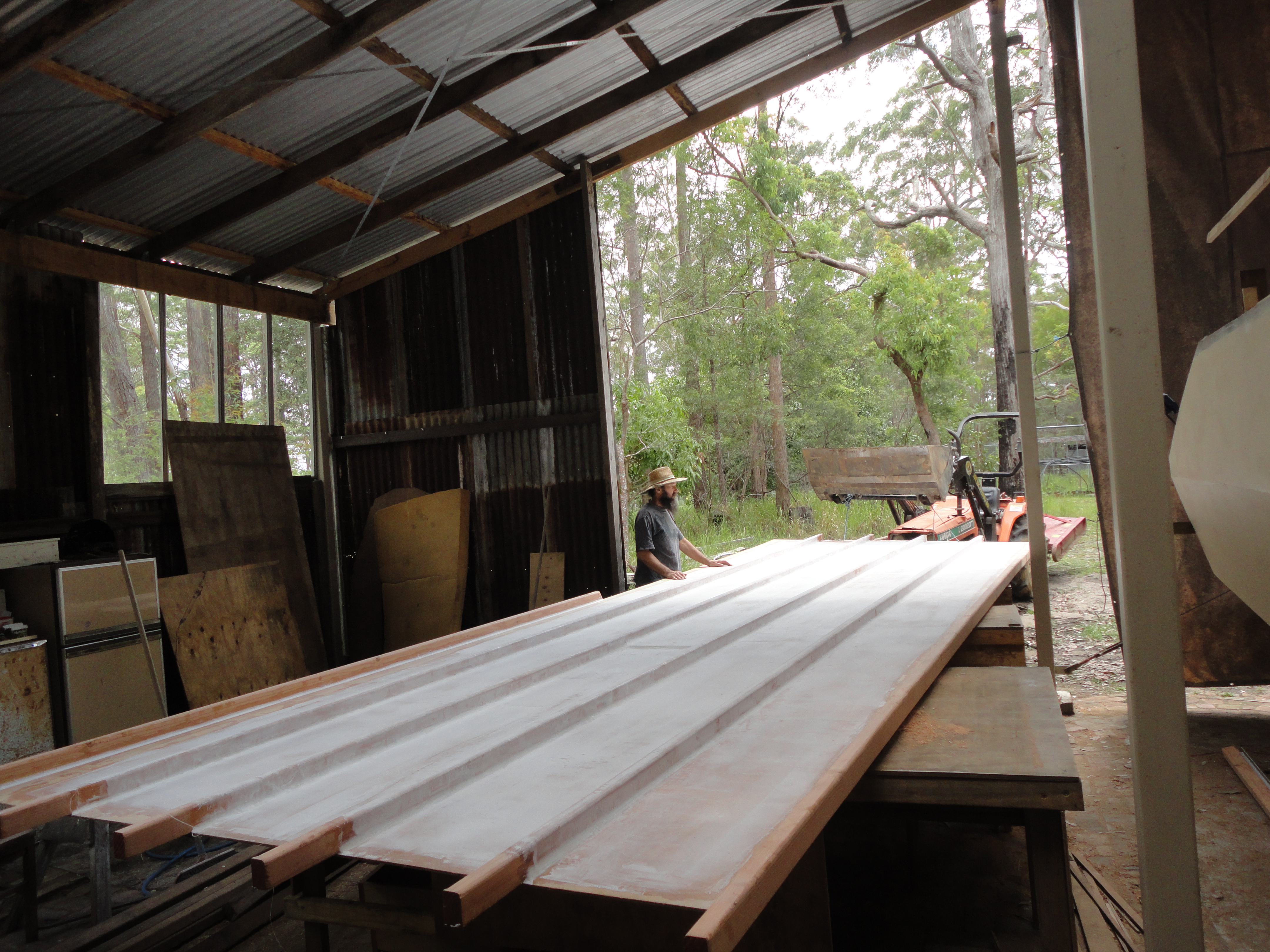
The sheets continue to the back. Each sheet is butt jointed with the previous sheet.

The electric planer was modified with wings added to the base plate. This allowed the plane to be aligned with the side of the boat, running the wing along the stringers. This then bevelled the chines to the correct angles. The first sheet edge is bevelled to the correct angle for the adjoining edge sheet, and the second sheet was then bevelled to the correct shape for the finished chine.
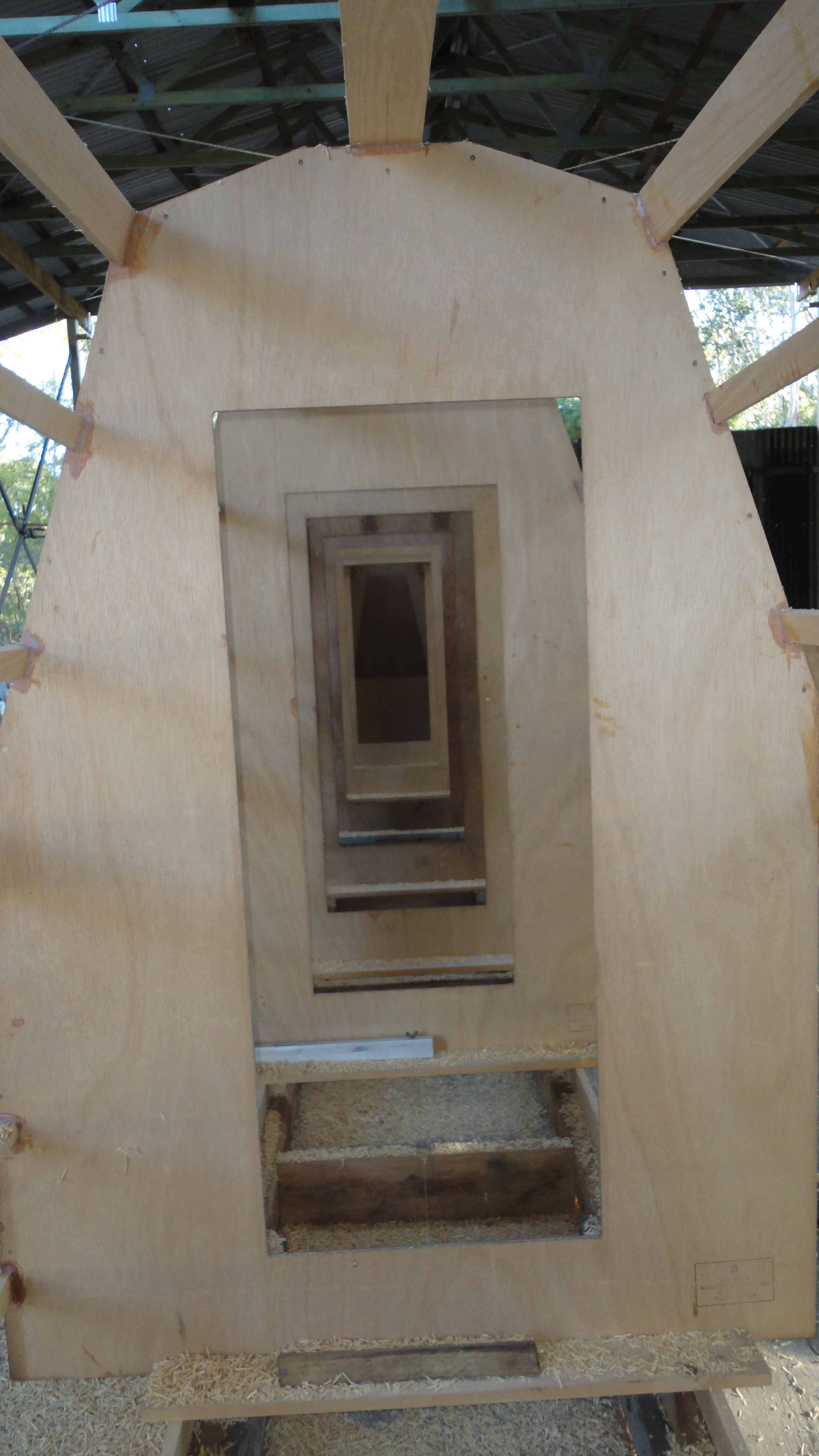
The CNC cut panels had precisely positioned cutouts through the cabin frames. This allowed us to visually check the alignment of the frames. We found that as the stringers and sheets were wrapped around the frames that twists could be introduced, and this view up the inside of the frames gave us a measure of whether that was happening.
And then finally the sheeting was complete.

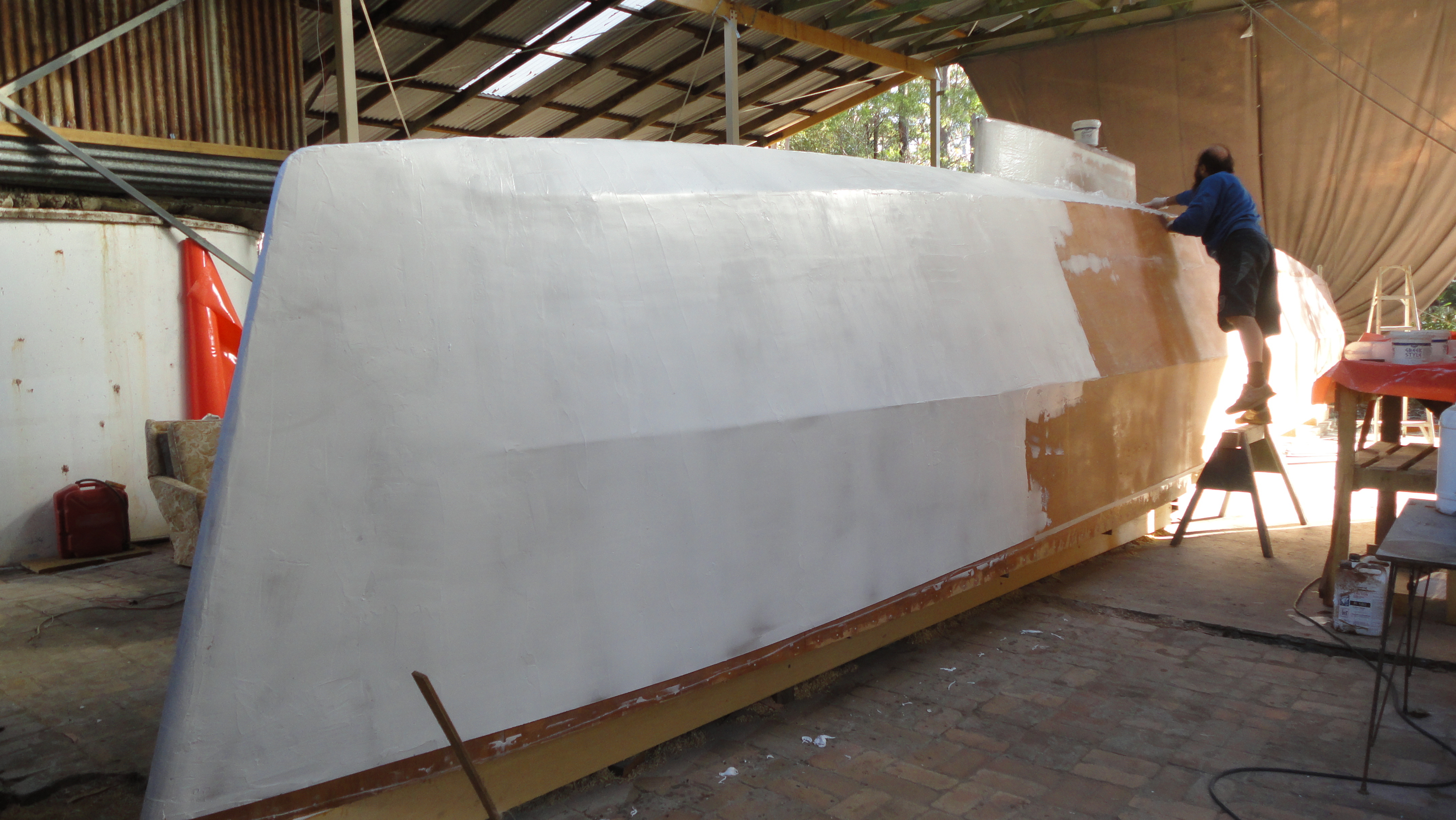
The finished hull was then coated in fibreglass cloth and epoxy resin. Extra layers of cloth went onto the keelson forward of the keel, and around the keel to hull joint. We worked hard to cover the outside of sides of the hull in one single length of cloth so to avoid having a double thickness join to fair out later.
The glassed hull was then bogged with an epoxy filler, closing the weave of the cloth.
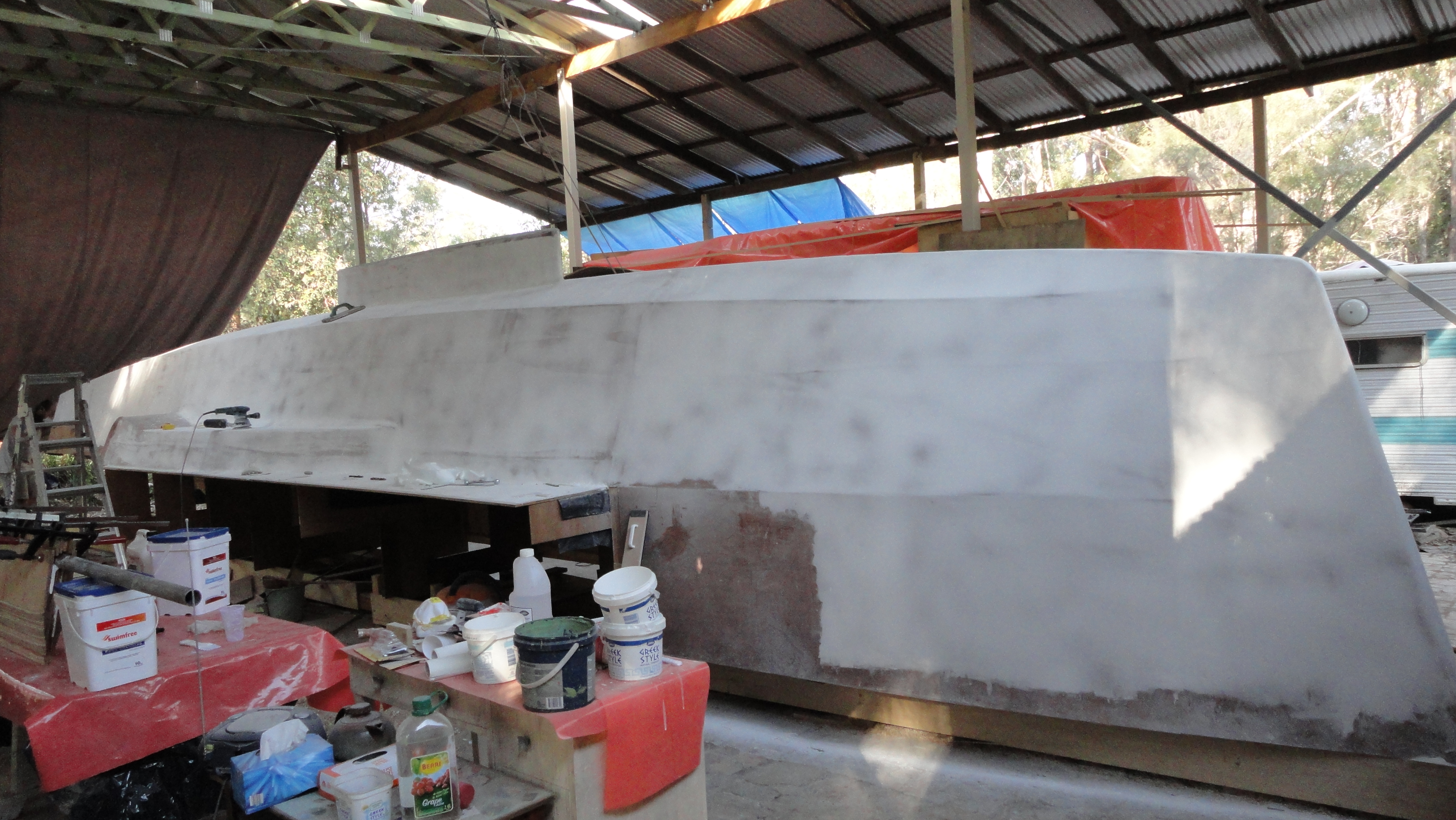
We stopped the edge of the bog back from the top of the hull, as the deck had to be later joined and the cloth overlapped.
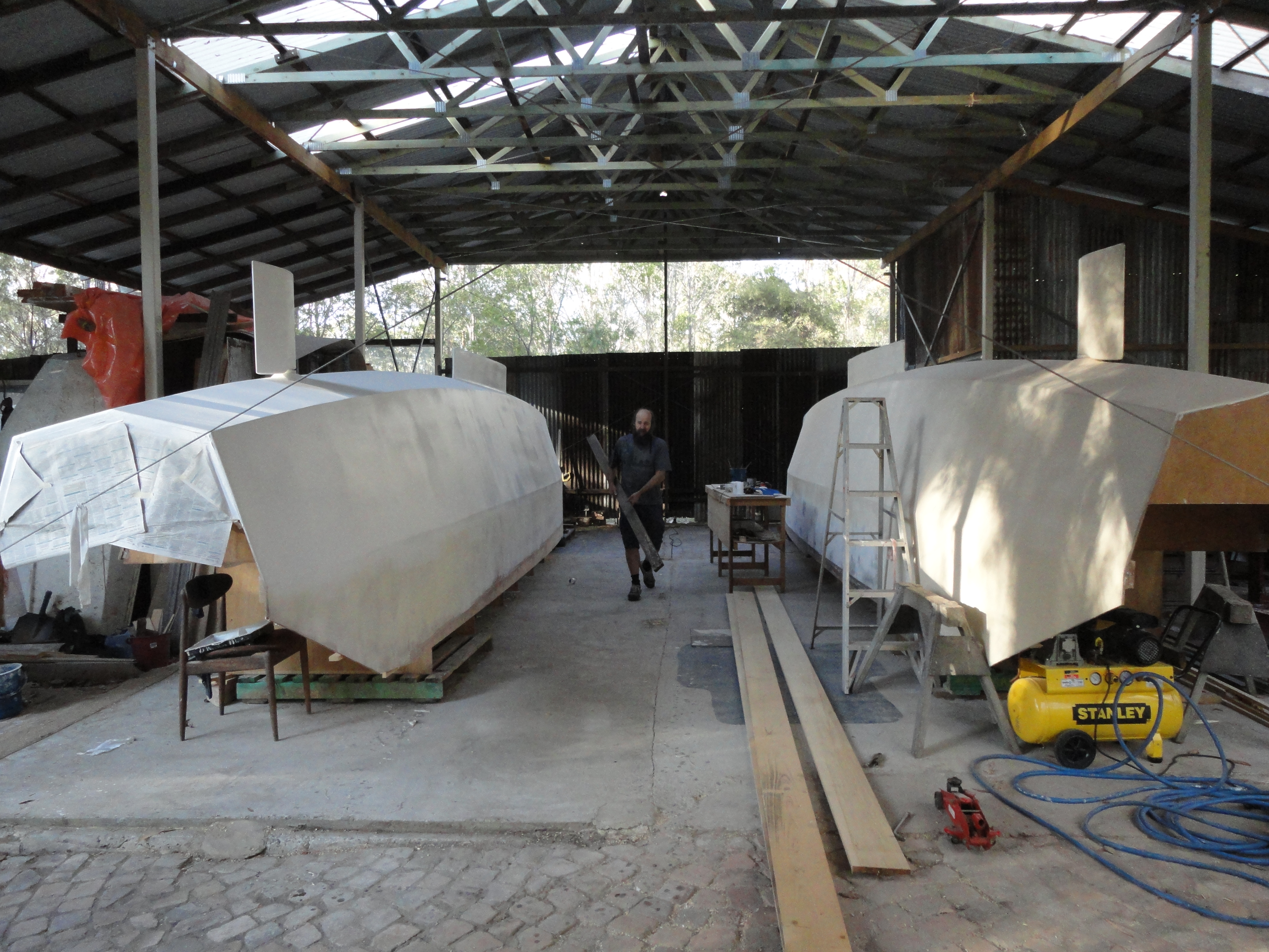
With that first hull complete, it was time to move it off the strongback jig and start all over again.
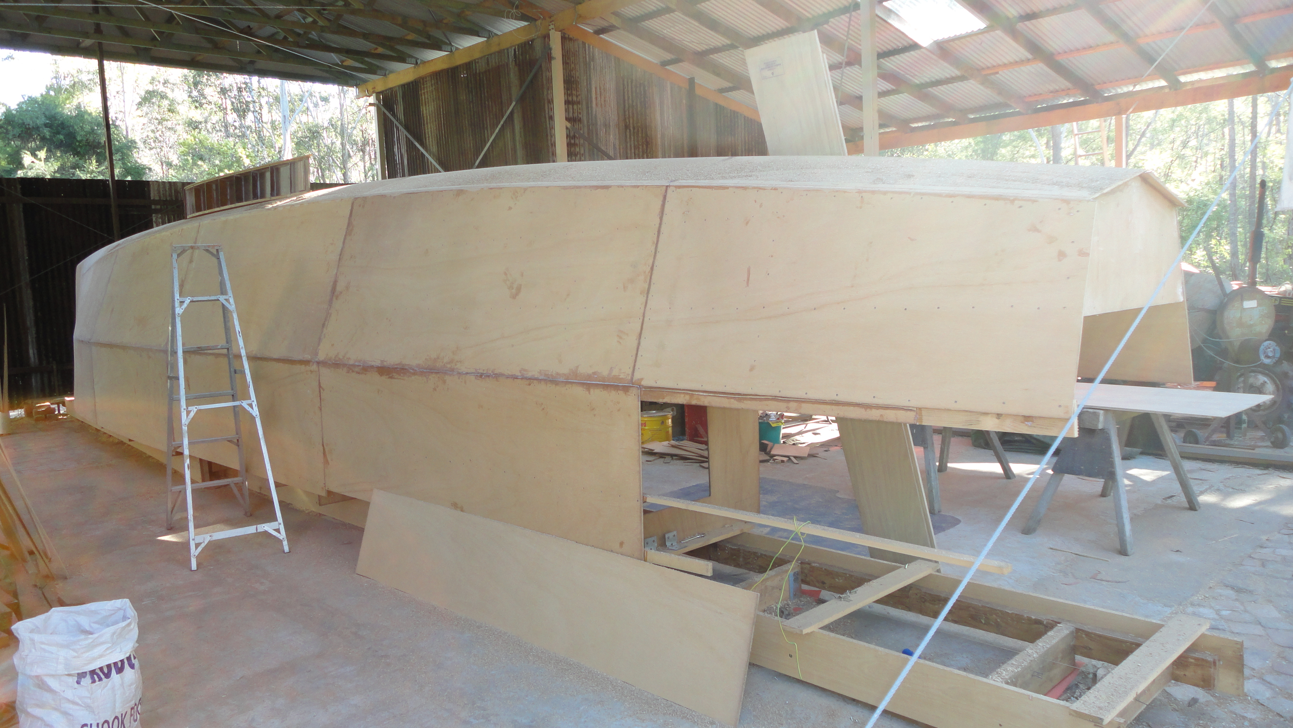
This photo shows the second hull being sheeted. The alternate sheeting pattern is obvious in this photo, and if you look closely, you will see that this hull has an extended outboard pod. We added the outboard pods to the hull frames before they were stood on the strongback, ensuring that they were an integral part of the frame instead of tacked in later.
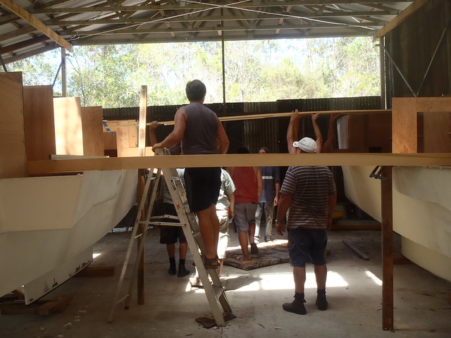
With both hulls finished, it was time to get a party of friends to help roll them over.
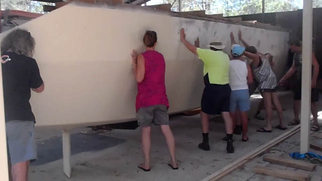
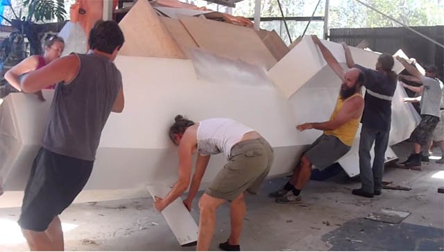
With enough friends to lighten the load, we simply lifted and rolled. We had some rugs on the concrete floor to eliminate scratches. Special attention was given to the rudders, as they want to tip and jamb on the floor which would put too much pressure on the rudder post.
With the hulls rolled over, the frames that join them together were first clamped on, helping to hold the hulls upright.
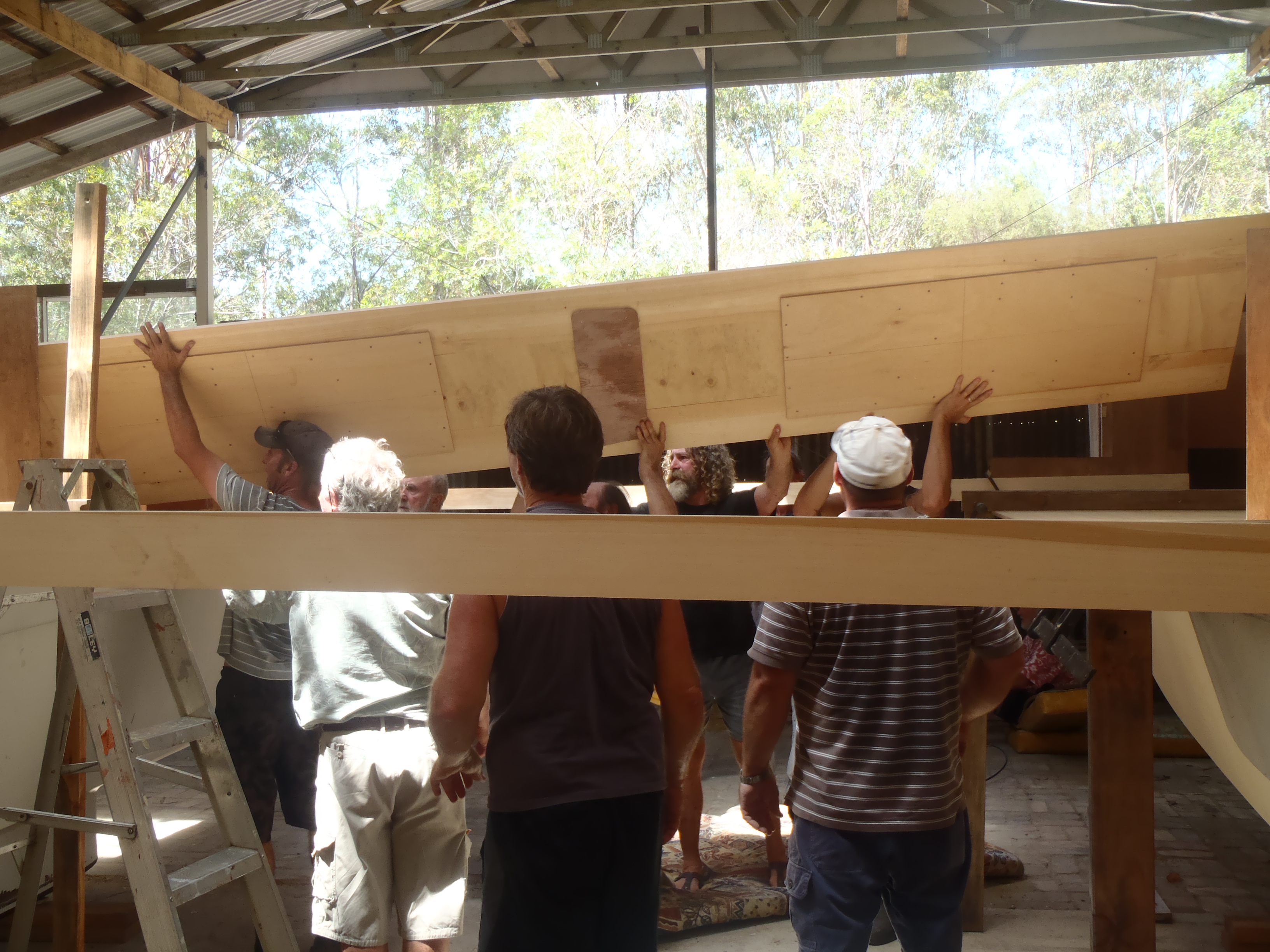
Here is “frame 5”, the big one that will one day support the mast, being lifted roughly into position. We spent the next few days carefully measuring the diagonals and levels to make sure everything was true before these frames were glued in.

Many thanks to all the friends that came to help with rolling the hulls, that very hot day in January 2014. From memory, I think it cracked 43 degrees. We all ended up sitting around the pool drinking beer that afternoon.

Once the hulls were rolled over, there were suddenly a multitude of jobs that could be commenced. Up till now, there had been one critical path on the project, but suddenly there was a choice. Join the hulls together with frames, start on the bridge deck, get inside the hulls and start cleaning it up for fitout. So much to do!
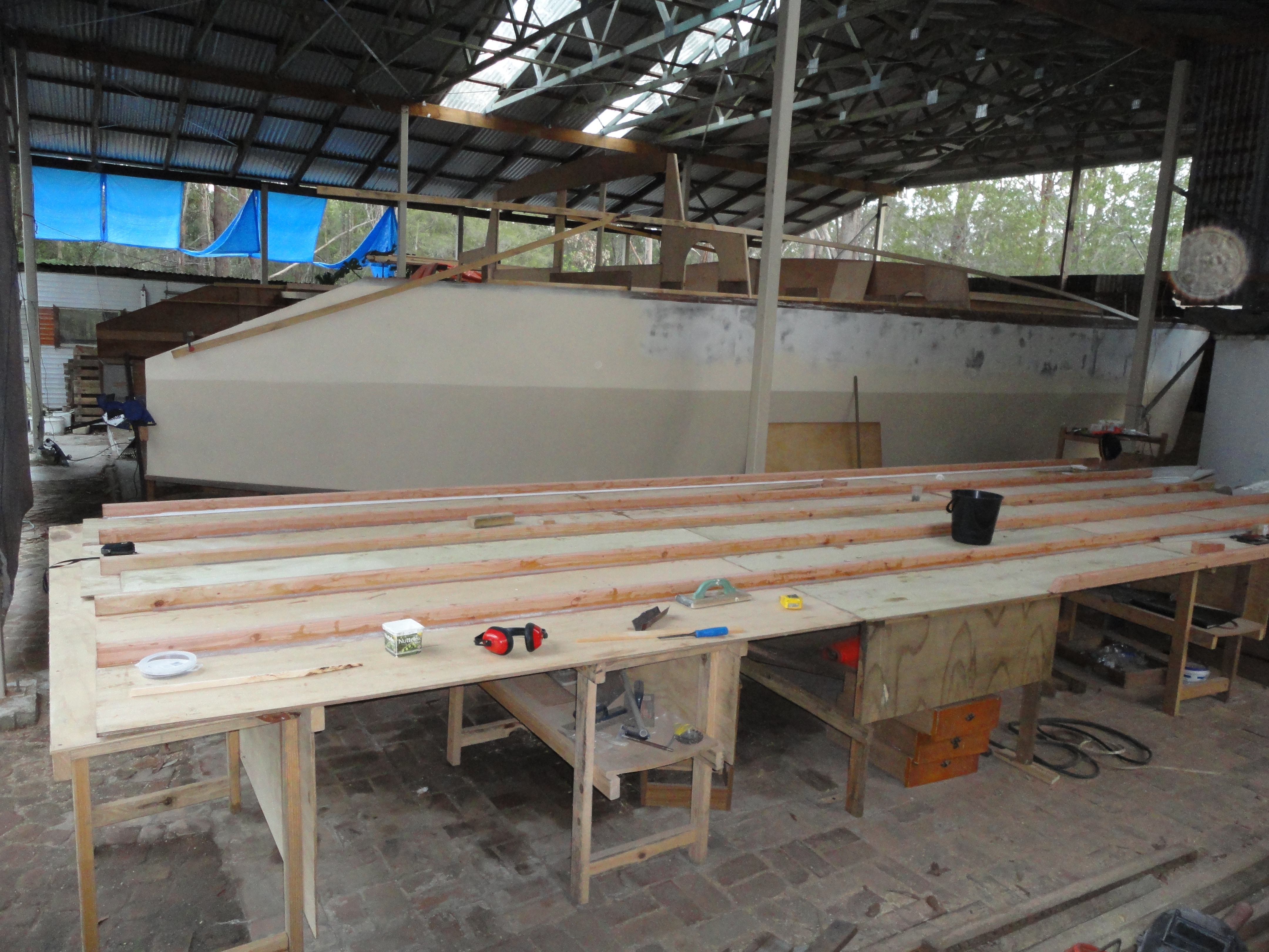
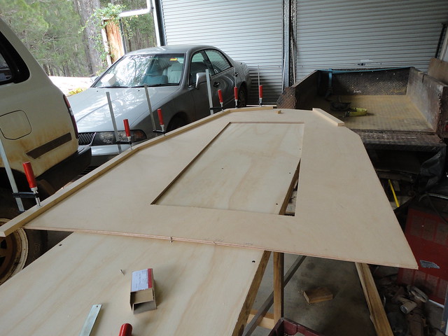
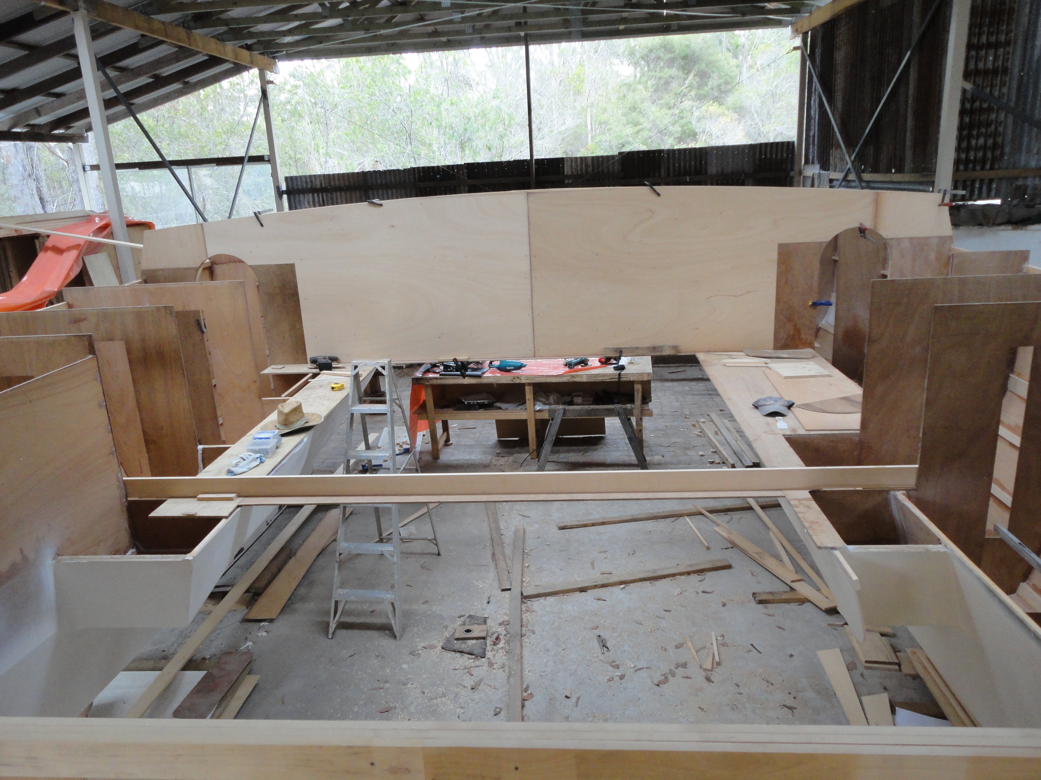
The bridgedeck was built from 6 sheets of 12mm plywood. As there was an excess to be cut from the end, I had the sheets rebated on Keith’s router to make for stronger butt joints. The stringers give it extra strength and take some of the bounce from the cabin floor. Here it is being assembled upside down.
With the stringers glued and screwed onto the plywood sheets, the corners were coved and the whole assembly covered in fibreglass cloth and epoxy resin. The edges were left clean, ready to bond onto the two hulls.
With the assembly complete and the glass cloth bogged over smooth, it is time to get it turned over and placed under and between the two hulls. We used our little tractor to lift it down to the ground, where we dragged it out to a clearing and rolled it over onto our bogie axle box trailer.
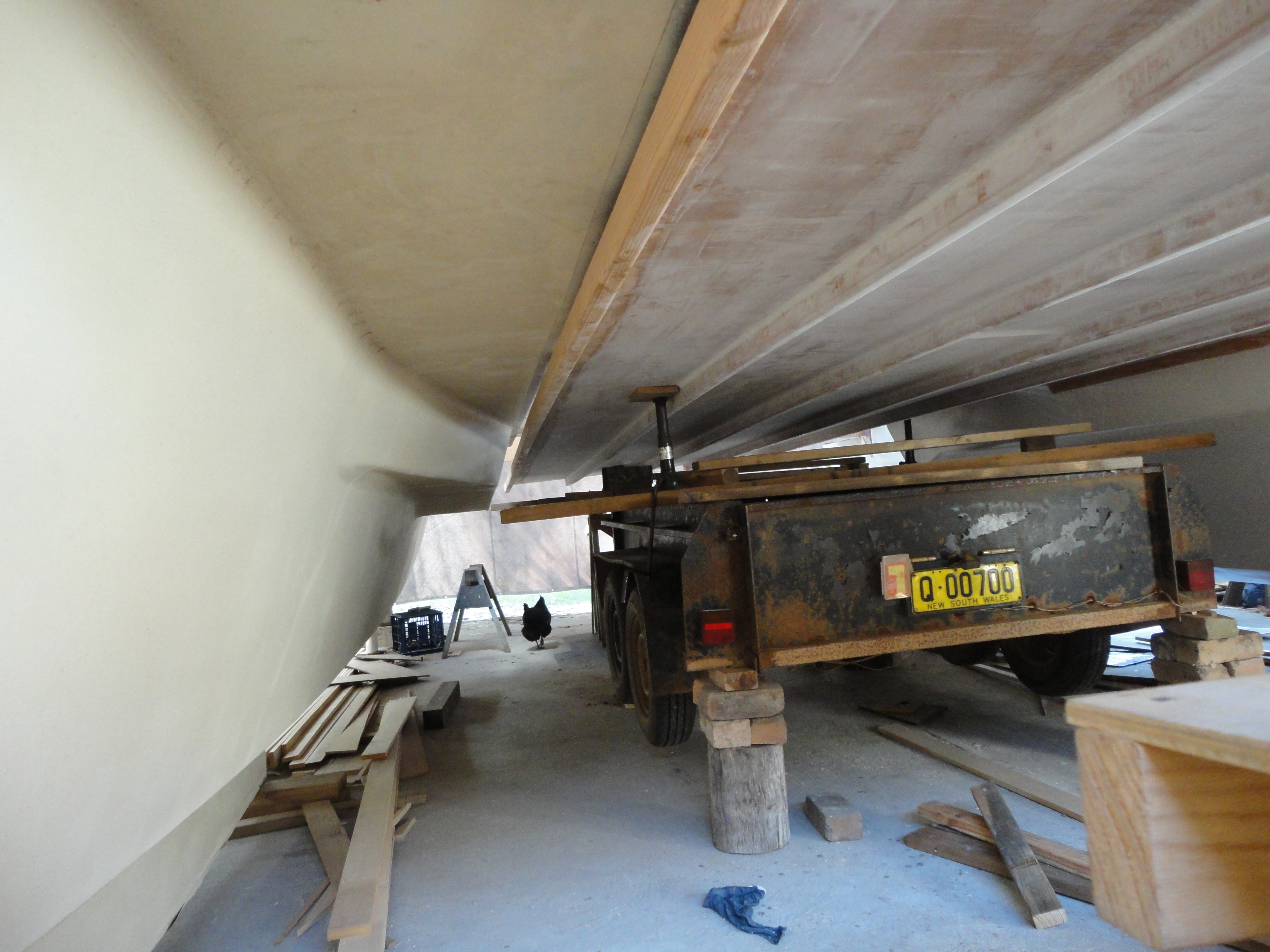
Here is the bridgedeck, on the trailer being positioned in underneath the frames the join the hulls. Once in location, the trailer was jacked and blocked to lift the deck up close enough to glue and screw it all together.
With the bridgedeck fitted, now there was somewhere to walk. The size of the whole project was starting to sink in. The floor in the foreground is to become the cockpit with one of the motors already sitting in the engine well. Having the motor available meant that we could ensure that everything fitted with clearance. You wouldn’t want a new motor sitting around depreciating, so it was good to have these old ones to use.

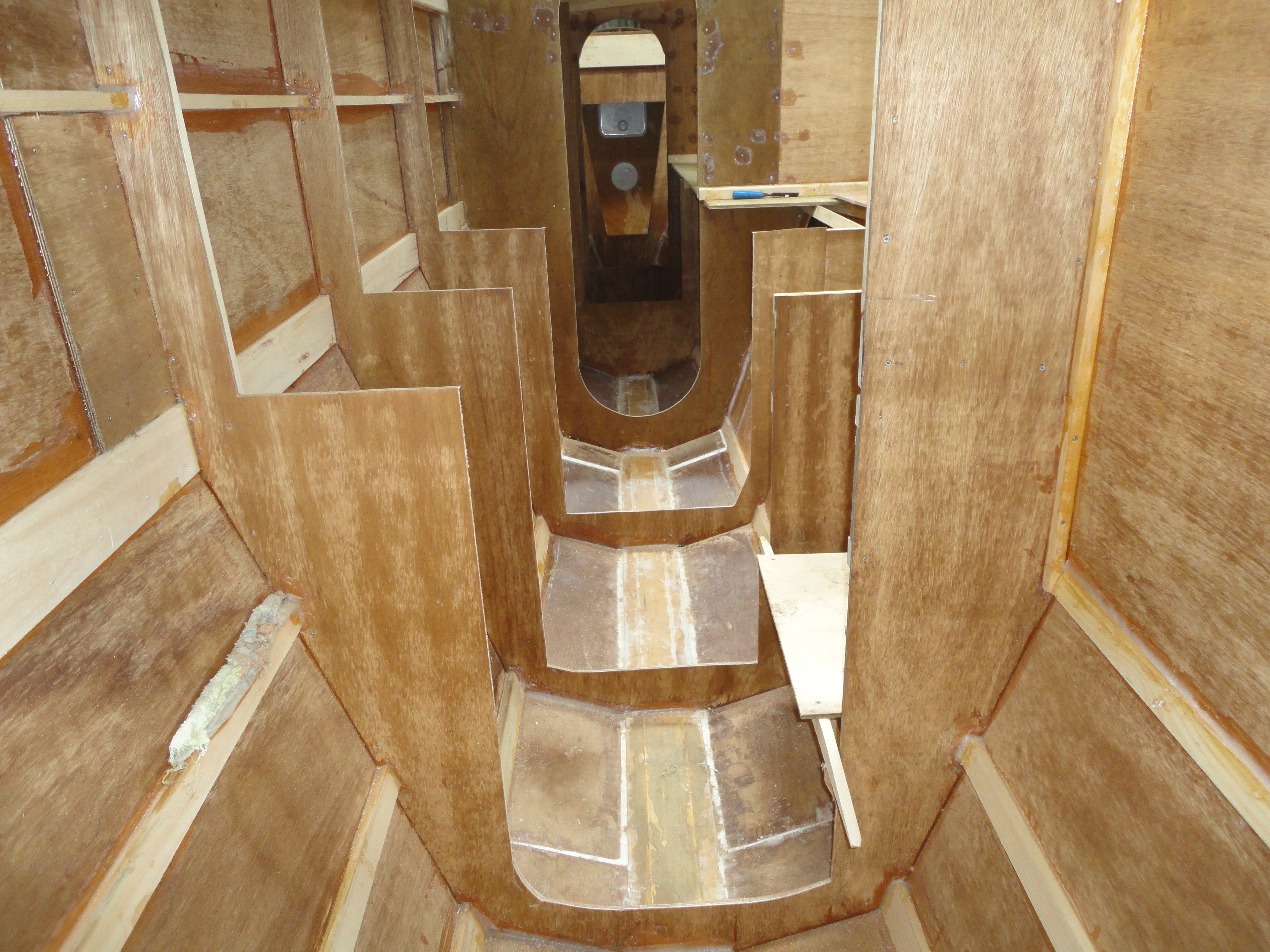
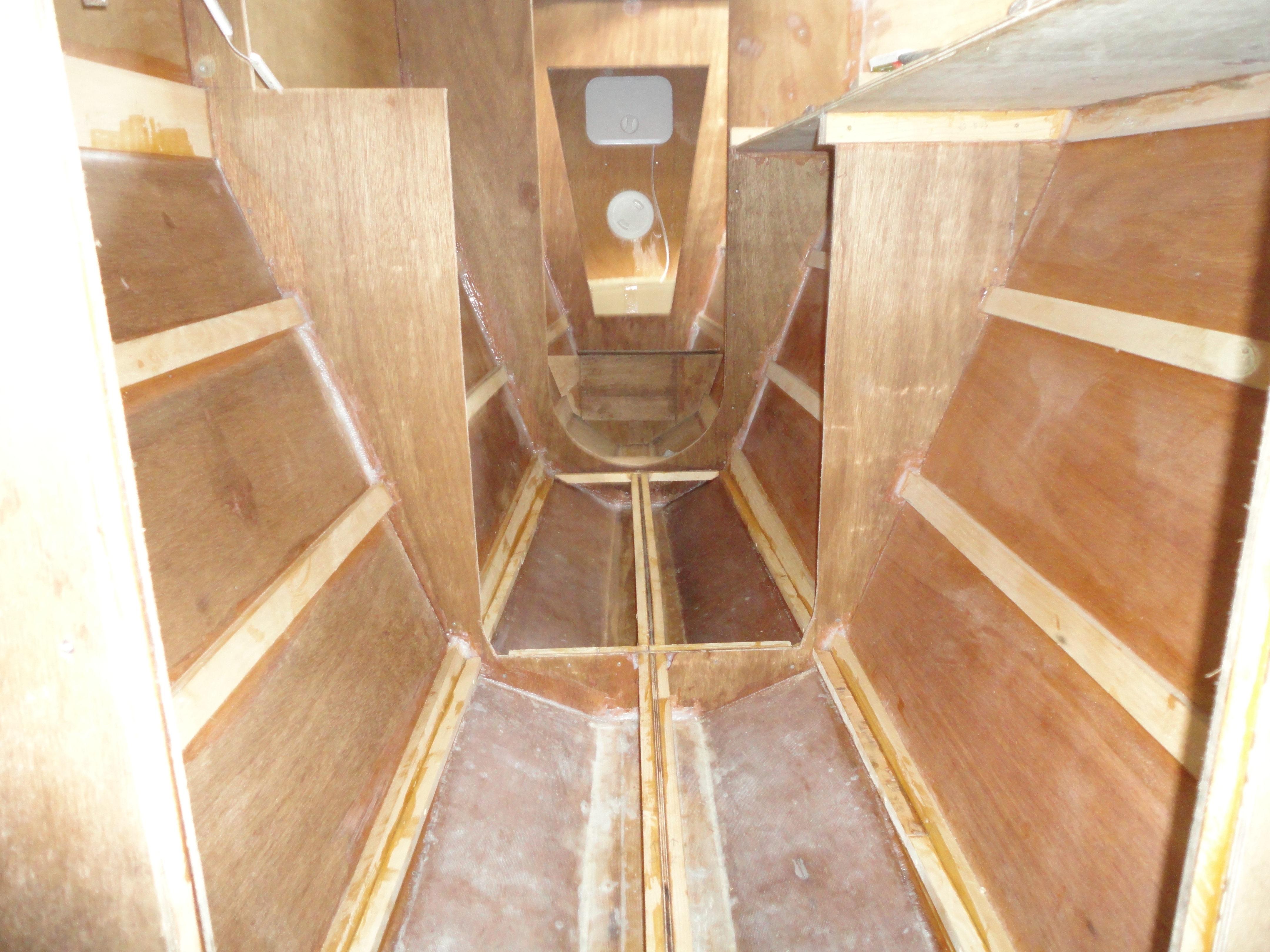
With the hulls upright, the inside of the subfloor void space was glassed and thoroughly wetted out with epoxy resin. Subfloor support framing was glued in prior to the floor being fitted.
On top of that subfloor framing, the floor of plywood was glued and screwed. But that plywood floor required a lot of preparation.
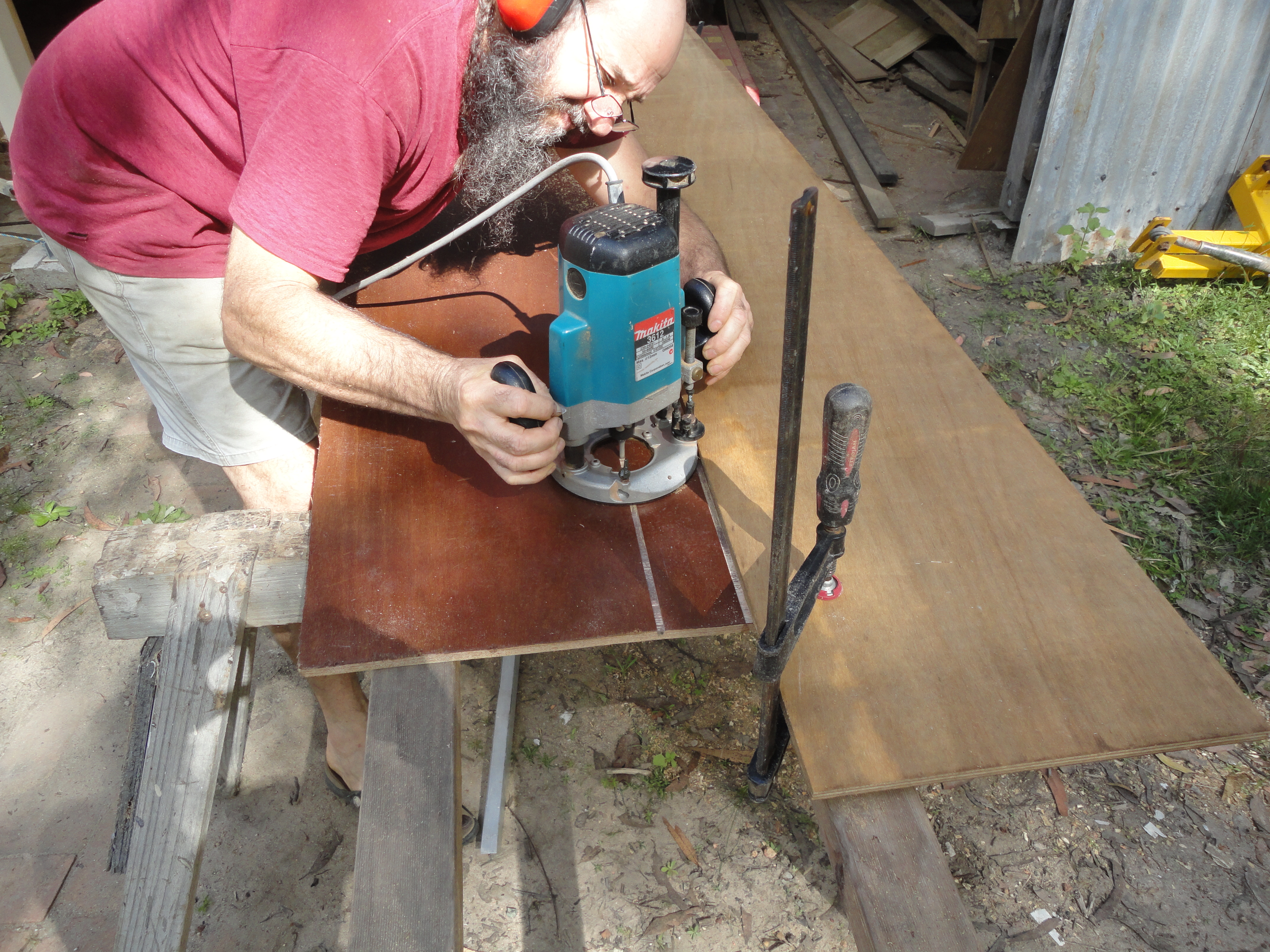
Here the plywood is being routed to simulate boards. It had been previously stained and varnished to protect the surface. The bottom of the router grooves allowed us to hide the screws.
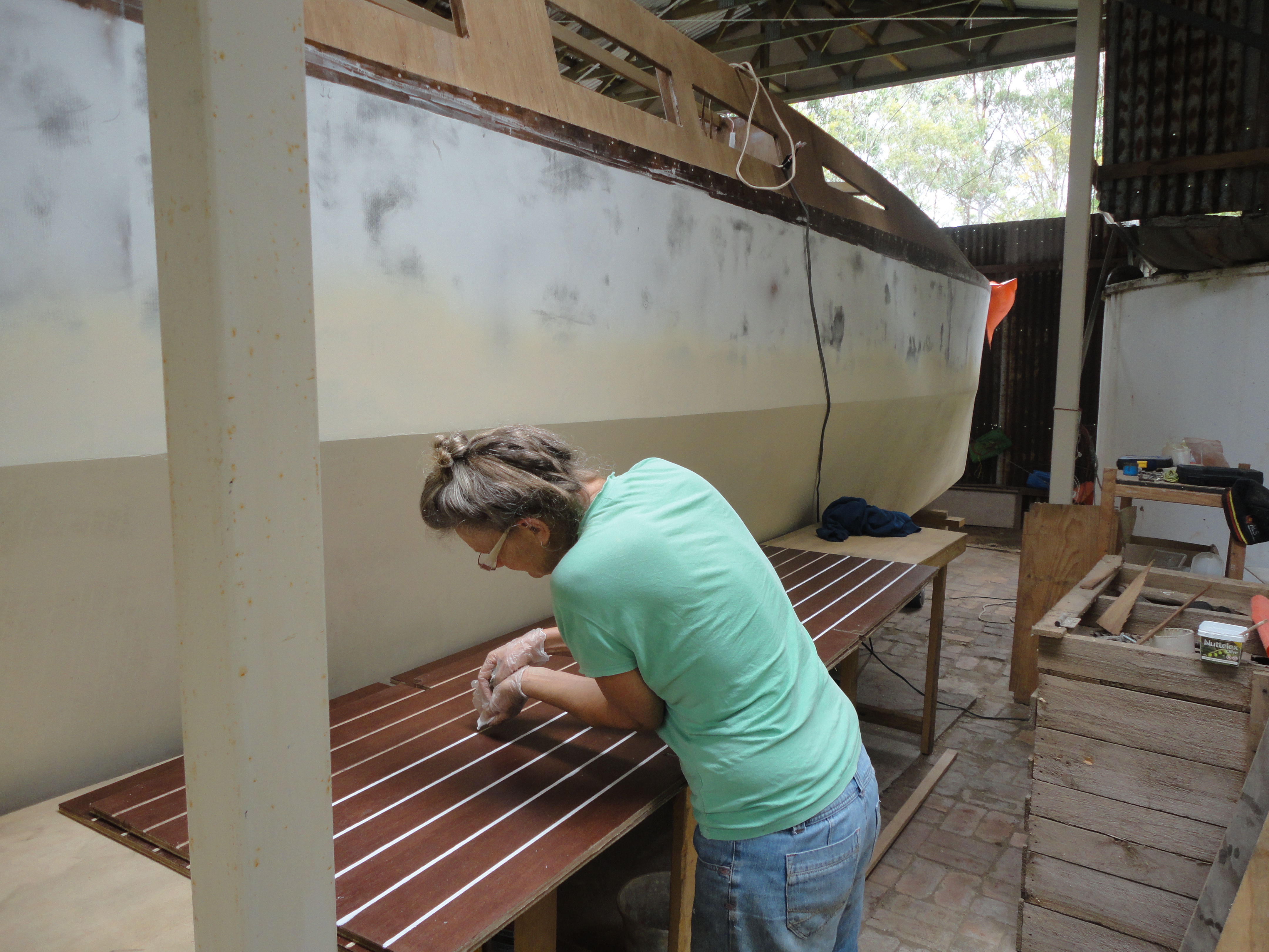
The grooves were first filled with white bog, using plastic bags with a corner cut out in the fashion of a icing piper on a cake. Something about the colour, texture and smell of the bog used to make me drool.
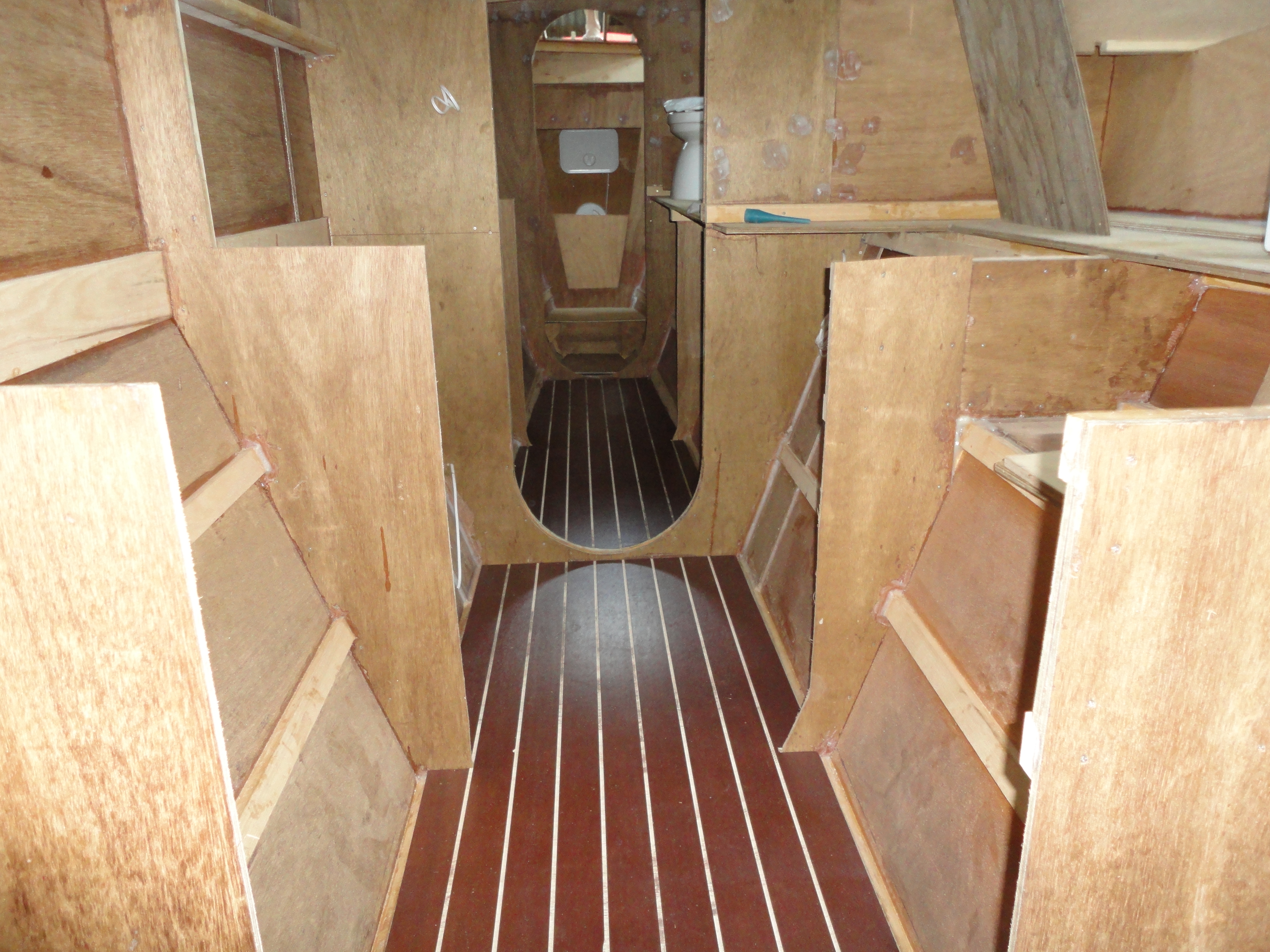
It took a bit of work to fit the floor into the space, with the minimum amount of space around the edges and around the cut outs for the frames. Once glued down, the screw holes were touched up and the edges coved in. We then sanded and re-varnished it all again before covering it with plastic to protect the surface during the building process.
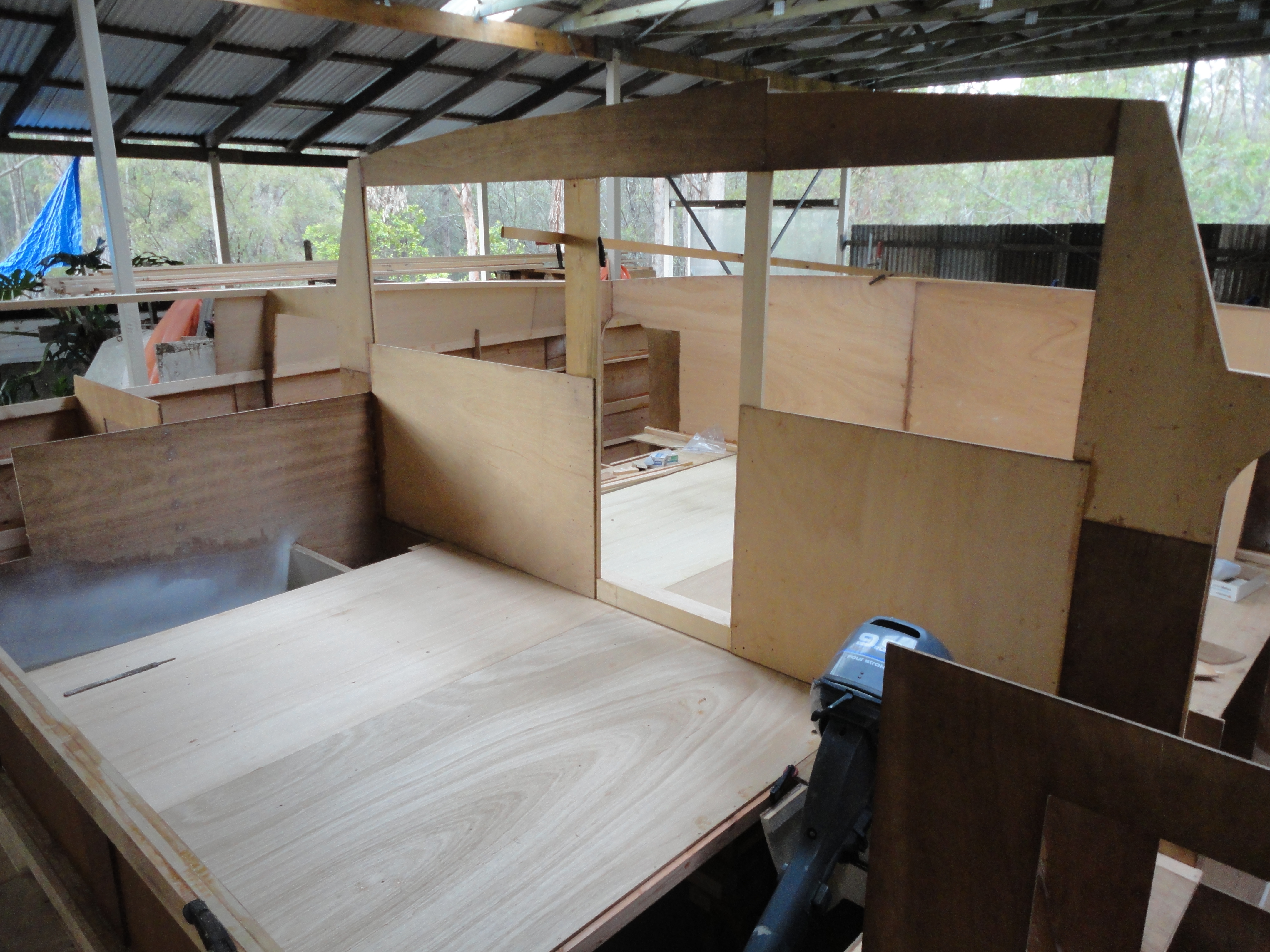
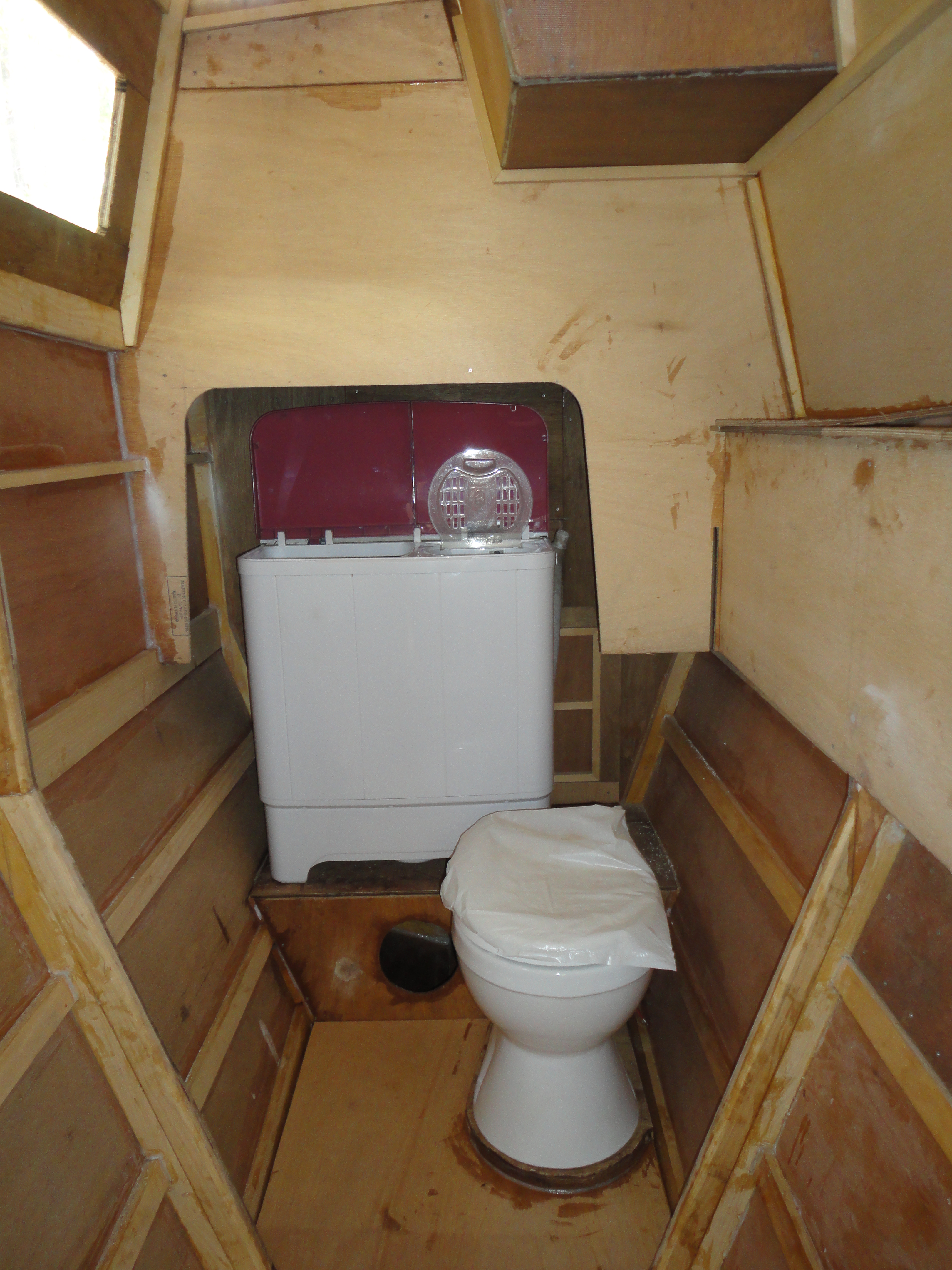
After the floor it was on to the lockers and deck. Large items like the stove, the head (toilet), washing machine, and so on, were sat in place while we figured how to build the lockers around them.

Here I was trying a prototype of the cupboard doors in the galley. Things that we had to consider with these prototypes included what type of hinges would work, how to hang them, how the door would seal, what type of catches, how heavy will they be, will they stay closed?
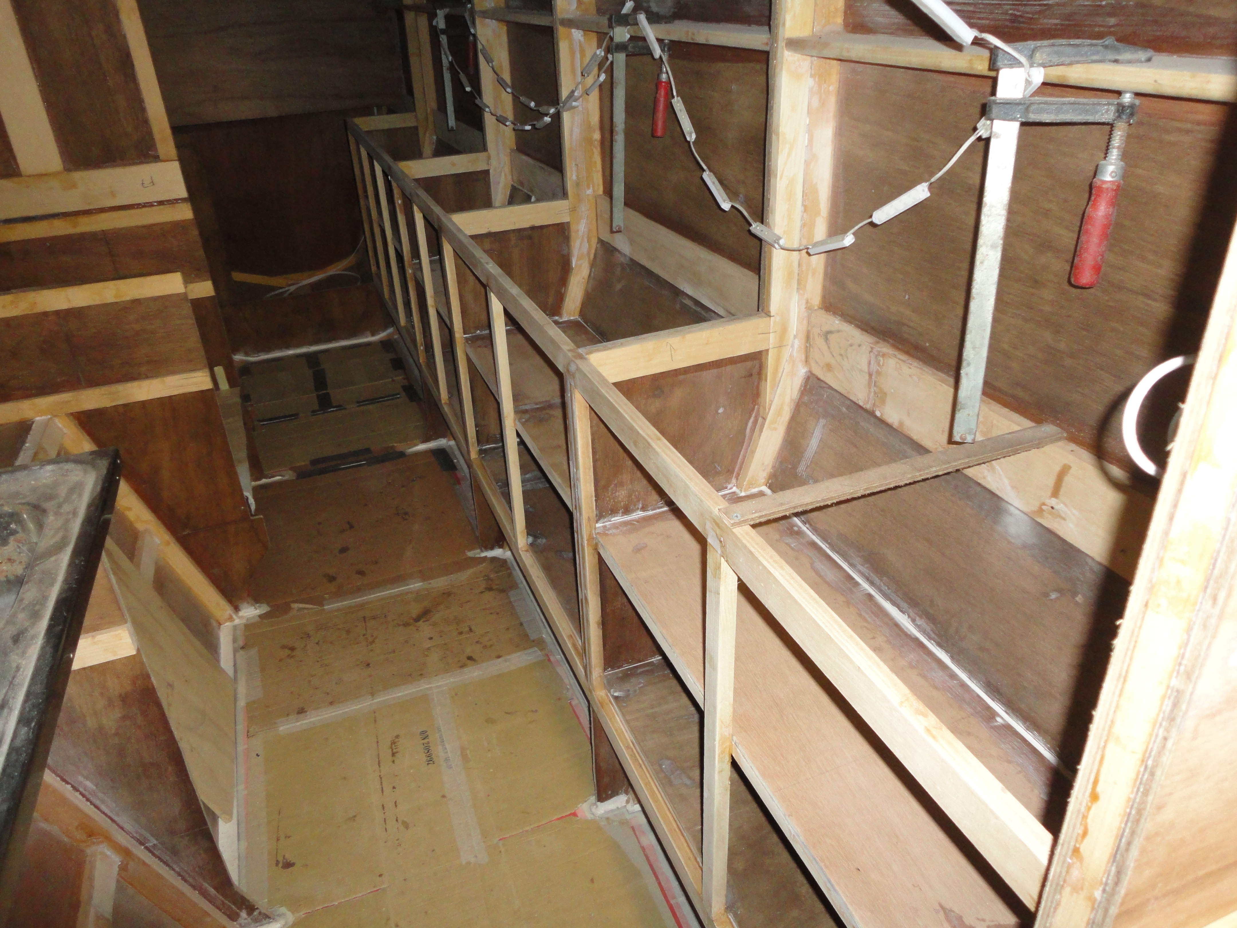
You can see here that the frames that had formed the shape of the hull have been removed above the cupboard height. That plywood has gone into forming the shelves of the cupboards, which are structural and add immense strength to the side of the hull.
… to be continued…
Beautiful job. Very inspiring
I’m about to embark on the same journey building a Waller 1200.
What type of cnc router did you use to cut the bulkheads and are they worth the investment
Cheers
Bernie
Ps have you heard anything good or bad about the Waller 1200